Water Meter Considerations
Advanced water meters come in a range of different specifications and capabilities, and not all advanced water meter products will be appropriate for each situation. Important considerations are included in the following sections.
Selection Considerations
Meter Size. The appropriate meter size depends on the anticipated flow range (minimum, maximum, and continuous duty), as well as the other considerations outlined here. The American Water Works Association oversees water meter specifications, including testing criteria, selection, installation, and maintenance guidelines. Per AWWA standards, threads on meter bodies are typically listed as one nominal iron-pipe size larger than the nominal size of the meter inlet internal diameter. Meter sizes indicated throughout these best practices refer to the flow capacity of the meter body internal diameter, not the nominal pipe size they are connected to.
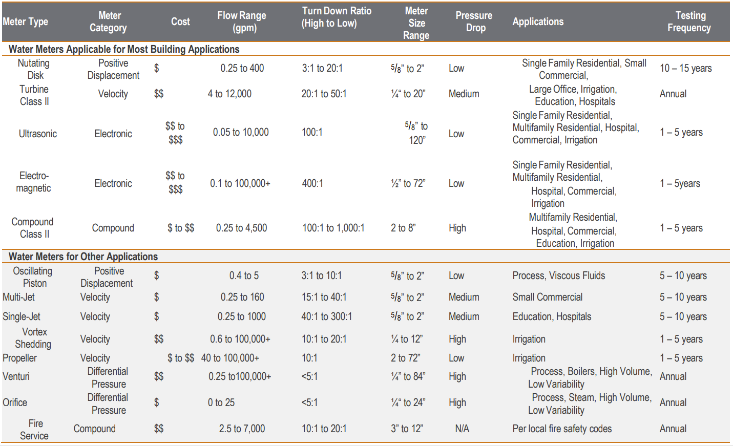
Manufacturer product data sheets will list meter characteristics similar to those noted in Table 1 specific to their sizing ranges.
Water Demand Profile. A water demand profile is the range of flow rates expected or observed throughout a time period, typically one week. For some buildings or applications, water consumption is consistent with little variation, while others may experience large swings in water use throughout the day, month, or season. It is imperative to select a water meter that can operate in the expected extended low-flow and maximum continuous duty ranges of the building or application.
Accuracy. Some applications may require highly accurate meter readings (laboratory equipment), while others may not require such high performance (irrigation). Accuracy is a function of the meter type, meter size, and the water volume and velocity flowing through it. The turndown ratio (TDR) is a metric that compares a meter’s highest rated flow range to its lowest. An oversized meter will not accurately measure low-flow rates, making it harder to detect problems at a building level. Meter accuracy also can be affected by improper installation. This is especially true for turbine and compound meters that require flow conditioning for a uniform swirl-free flow profile in the pipe immediately upstream of the meter.
Pressure Loss. Meters can impart a pressure loss to the system from friction through the flow path of the device, especially for mechanical meters. Some meters (electronic and ultrasonic) impart minimal drag on the water flow, while others (venturi) depend on water pressure to register measurements. Undersized meters may have a large pressure drop; however, larger meters may not measure low flows as accurately and have high cost and installation disadvantages. Determine the building or application acceptable pressure loss and select a meter that fits within this pressure range or provide provisions to compensate for proper system operation, such as a booster pump.
Location. Meters can be located indoors or outdoors, with each option having advantages and disadvantages. For example, indoor installations provide protection from the elements and added security but may require a significant footprint in the mechanical or water entry room. Outdoor installations may free up valuable indoor space, but the location of the underground meter vault may interfere with vehicle or foot traffic. Other considerations include access for reading and maintenance, meter harmonics/vibrations local drainage, and freeze protection for outdoor applications.
Available Space. The space required for meter installation depends on the type, size, and required accessories (straight lengths of pipe, strainers, control valves, test ports, etc.) that make up the “meter set.” Allow sufficient space around the meter set to permit access for reading, testing, calibration, and maintenance.
Networking and Cybersecurity. As advanced metering infrastructure (AMI) is increasingly integrated with federal IT networks, advanced meters introduce new entry points for potential cybersecurity breaches. Close coordination between agencies’ facility operations and IT personnel is essential to ensure that potential vulnerabilities are addressed and that AMI systems are operating in accordance with federal information cyber security policies.
Communication and Data Management Systems. Communications and interoperability between meters and other data acquisition systems are critical. Confirm meter communication options are appropriate and compatible with existing IT systems and cybersecurity protocols. Current AMI and advanced meter reading (AMR) technology allows for remote data readings, minimizing previous disadvantages of indoor or outdoor installations. Confirm cybersecurity requirements with the appropriate federal agency’s meter acquisition policy, if applicable.
Cost. Initial costs vary by meter technology and size. A small turbine meter will be less expensive than an equivalent sized compound meter. An ultrasonic meter (newer technology) may be slightly more expensive to a comparable compound meter but may have other benefits, such as reduced footprint and maintenance. Procurement and installation should be balanced with operations and maintenance for the application. A low-cost meter which is not well suited to the application may cost more in operations and maintenance. Conversely, a more expensive compound meter may not be appropriate for an application where a less expensive disk meter may suffice. In certain cases, high costs could mean advanced metering is not practicable at some federal buildings. See the Federal Metering Guidance for an explanation of practicability of advanced metering in appropriate buildings.
To assist in evaluating the cost-effectiveness of advanced metering at a building or site, please visit the Advanced Meter Cost-Effectiveness Calculator website.
Installation Considerations
The following rules of thumb provide general guidelines for meter installations. Refer to the meter manufacturer’s installation recommendations for specific requirements.
- Install the meter in the proper orientation. Some meter types (electronic) can be installed in any orientation, while most others must be installed horizontally.
- Locate meter so it is readily accessible for reading, servicing, calibrating, and testing.
- Provide high-quality shutoff valves and connections so the meter can be removed from service without negatively affecting operations.
- Provide a bypass to allow for testing and routine maintenance without interrupting service.
- Provide for permanent electrical grounding not connected to the meter to prevent accidental shock to operations personnel.
- Provide protection from freezing and other conditions that could damage the meter set.
- Provide proper wiring connection to AMI/AMR or building controller system in accordance with individual federal agency IT and/or AMI/AMR requirements.
- For outdoor installations, confirm that soil conditions, groundwater level, frost line, and meter vault depth and clearances are appropriate.
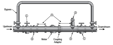
Pipe fittings and valves close to the meter introduce turbulence in water flow, which decreases the accuracy of most meters. The guidelines listed below and as illustrated in Figure 3 can assist in providing the best flow and measurement accuracy through the meter.
- Straight Pipe. Compound and turbine meters require a minimum length of five pipe diameters upstream and downstream of the meter for optimum performance. For example, a pipe 3” in diameter would require 15” of straight pipe both upstream and downstream of the meter.
- Strainer. Water that contains sediments or contaminants can damage or interfere with the internal components of most water meter types. Although some meters include internal strainers, installations without an appropriate external strainer may require a minimum of 10 pipe diameters of straight pipe upstream of meter.
- Valves. Valves disturb water flow, thus interfering with the water flow profile.
- Install full open butterfly or gate valves a minimum of five pipe diameters from meter and strainer upstream and five pipe diameters downstream.
- Install check valves at least five pipe diameters downstream of the meter. Install pressure reducing valves at least five pipe diameters downstream of meter. Never install check valves or pressure reducing valves within five pipe diameters downstream of the meter.
- Other. Components, such as backflow devices, pumps, and test ports.
- Install backflow devices at least five pipe diameters upstream of the meter.
- Install test ports at least two pipe diameters upstream and downstream of the meter.
- Never install valves on the suction side of a pump near a meter.
Testing and Calibration
Most water meters, besides electronic types, contain moving parts that wear out over time and reduce accuracy and reliability. To avoid wear-related problems, it is recommended that meters be tested for accuracy in accordance with manufacturer’s recommendations or applicable AWWA test procedures for the meter type. General practices for maintaining different sized meters are listed below and provided by meter type in Table 1.
- Meter sizes between 5/8” and 1” should be tested every 10 years.
- Meter sizes between 1” and 4” should be tested every 5 years.
- Meter sizes above 4” should be tested annually.
Refer to the National Institute of Standards and Technology Fluid Metrology Calibration Services website for more information.
Water Meter Characteristics
Selecting the appropriate water meter requires identifying the unique requirements of each application. For example, a smaller meter may impart a pressure loss in the system and the cost savings and installation limitations may offset increased pressure load on the system. In a retrofit application where a building may not be able to be taken offline to install an inline meter, a clamp-on ultrasonic meter may be more appropriate. Further, some meter types are more appropriate for process loads or large volumes, such as agriculture or municipal scales. Table 1 outlines the primary considerations when selecting a water meter for buildings and other applications.
Water Meter Technology
The single function of a water meter is to convert the physical flow of water into a measurement of volume. While the process used to make this measurement varies, all water meters share these basic components:
- A coupling connection to the water line – Flanges and union threaded ends are the most commonly used connections. Ultrasonic meters can be installed with an adjustable strap outside the pipe.
- A metering element that reacts proportionately to flowing water – This could be an impeller, a nutating disc, or an electrical signal.
- A register that converts the incoming signal, pulse, or mechanical movement into a measurement of volume – In advanced meters, the register often is connected to an AMR/AMI system that transmits readings, often by radio frequency.
A variety of water meters are available on the market. Table 1 provides a general comparison of key attributes that can be useful in the selection process, with the most common meter types encountered in building applications.
Positive Displacement Meters
Positive displacement (PD) meters directly measure water volume by monitoring how often a fixed volume measuring chamber is filled with and emptied of water.
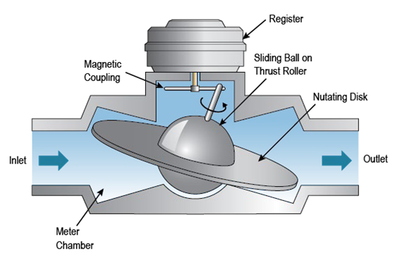
Types: There are two main categories of PD meters: 1) nutating disk and 2) oscillating piston.
- Nutating disk meters have a disk on a sliding ball guided by a thrust roller. The movement of water into the fixed volume measuring chamber causes the disk to nutate, or wobble, on its axis. The thrust roller is connected to a magnetic coupling at the register.
- Oscillating piston meters have a precision-machined measurement chamber containing a circular piston constrained to oscillate in one plane only. The rotation of the piston within a circular groove is transmitted to the register either mechanically or magnetically.
Applications: PD meters are well suited for smaller systems with low-flow rates, up to 400 gallons per minute (gpm). Common PD meter sizes range from 5/8” to 2”. Nutating disk meters are the most common type of PD meter used in building applications. Oscillating piston meters are ideal for use with viscous fluids, such as in vehicle maintenance and food and beverage applications.
Selection Tips: PD meters are very accurate for low-flow rates. Pressure drop through the meter is modest, and meter maintenance is minimal. Smaller low-occupancy buildings are ideal candidates for these meters, as are low-flow applications. PD meters operate best when installed horizontally. PD meters are small and do not require straight lengths of pipe upstream or downstream of the meter and are well suited for environments where space is limited. As the measuring mechanism is not designed for higher flows, buildings, or applications that experience periodic high-flow rates should consider a compound meter. PD meters are less expensive than comparable turbine or compound meters.
Velocity Meters
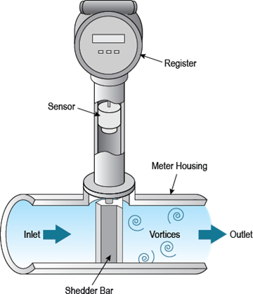
Velocity meters measure water velocity and convert the measurement into a volume. An impeller spins at a rate proportional to the water flow. In the case of a vortex shedding meter, volume is interpreted through flow-induced vortices.
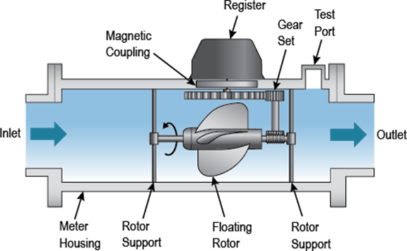
Types: There are four main categories of velocity meters: 1) turbine, 2) single-jet and multi-jet, 3) vortex shedding, and 4) propellor.
- Turbine meters use an impeller connected by a gear set to the register to measure the water flow. There are two classes of turbine meters. Class I turbine meters have the impeller axis perpendicular to the water flow; they tend to be older designs and thus are less widely used. Class II turbine meters have the impeller axis parallel to the water flow and are smaller than Class I meters.
- Single-jet and multi-jet meters concentrate the flow of water into several columns directed at the periphery of an impeller. Single-jet meters have one jet directed tangentially to the impeller. Measurements are taken in a similar manner as turbine meters.
- Vortex shedding meters are unique as they induce vortices in the flowing water and use the frequency at which these occur to measure the flow rate and infer the volume.
- Propeller meters have a “pinwheel” (rotor) in the flow stream that spins on a horizontal axle geared to a register. The rotor spins proportionally to the fluid velocity with minimal pressure drop. This meter type can measure high-velocity turbulent flows and can be used in water in which particulates are present without significantly affecting the meter components.
Applications
- Turbine meters should range in size from ¼“ to 20” and work best in high-flow applications, thus should be considered for high-occupancy facilities and end uses where flow rates are greater than 50 gpm.
- Single- and multi-jet meters range in size from 5/8” to 2” and cover a wider range of flow rates ranging from 2–30 gpm.
- Vortex shedding meters range in size from ¼“ to 12”. They are less common in potable water applications, as low-flow rates are not accurately measured. However, they can be appropriate for end uses with continuous moderate to high-flow rates, such as boiler feed water, chilled or hot water systems, corrosive fluids, or where moving parts are not desired.
- Propeller meters range in size from 2” to 72” and are most appropriate for high-flow end uses containing sediments, such as irrigation mains.
Selection Tips
Acceptable flow rates vary from meter to meter in this category; consult manufacturer data sheets to help select the appropriate meter. Avoid installing turbine meters in buildings or end uses in which frequent low-flow rates are experienced, as accuracy in these ranges tends to be poor; PD or multi/single-jet meters would be better choices for that application. Turbine meters need fully established and a relatively steady flow profile upstream of the meter. A strainer should be installed upstream of the turbine meter to remove debris that can impact accuracy and reduce the life of the meter. Many turbine meters require an adequate length of straight pipe installed before and after the meter (typically 10x and 5x nominal diameter, respectively) otherwise accuracy will be affected. Vortex meters should be avoided in applications where intermittent, low-flow rates occur due to the possibility of under measurement.
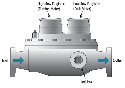
Compound Meters
This meter type uses a combination of both high- and low-flow metering devices for facilities with a wide variation of water flow rates throughout a given period. Compound meters typically include both turbine and PD (disk) meters as one unit. When water usage is low, the PD meter is active and registers usage until flow increases above a threshold when the turbine meter registers usage. Accuracy is affected by the changeover point, which is the flow rate at which the meter transfers from the high- to low-flow measurements.
Types: There are three main types of compound meters: 1) series, 2) parallel, and 3) fire-service.
- Series compound meters operate simultaneously with a ratcheting mechanism so only one meter registers flow at a time.
- Parallel compound meters operate one at a time and transition by an automatic bypass.
- Fire service compound meters are specialty types listed by Underwriters Laboratories and/or Factory Mutual Global for fire service applications. This type of meter complies with applicable fire and life safety codes and standards.
Applications: These units have a large TDRs and are widely used in buildings and applications with large water flow rate variations. Common compound meter sizes range from 2” to 8”.
Selection Tips: Observe the use patterns (water demand profile) of each facility to minimize time spent operating at the changeover point. Also, consider the space needed to accommodate manufacturers’ recommended strainer and straight-pipe requirements. Compound meters ranging in size from 2” to 8”. When use is intermittent and shows significant variation, a compound meter should be considered. Because they require two meters per application, compound meters tend to be relatively expensive compared to a similar size turbine or PD meter.
Electronic Meters
Electronic meters measure water velocity from an electrical charge or signal and converts that measurement to a volume measurement. The measurement is proportional to the velocity, which is used to calculate the volume of water. Some electronic meters may include pressure and temperature sensors. Because the flow is through an open pipe with no moving parts, they can be installed with minimal to zero straight runs of pipe (depending on manufactures’ installation instructions); there is very little pressure drop and minimal maintenance required.
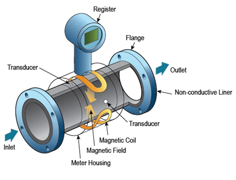
Types: There are two main types of electronic meters: 1) electromagnetic and 2) ultrasonic.
- Electromagnetic meters operate by sending a magnetic field through the water flow to induce an electrical current that is proportional to the flow rate moving through the field.
- Ultrasonic meters come in two varieties: 1) doppler and 2) transit-time.
- Doppler meters send and receive high-frequency sound waves through the fluid. The sound waves are reflected off particles suspended in the fluid and sensed by the metering unit. A shift in frequency is interpreted to arrive at the total water flow.
- Transit-time meters send an ultrasonic signal through the water, both in the direction of flow and in the reverse direction. The difference in travel time is proportional to the velocity of the flow. These meters are commonly found in non-invasive, clamp-on units that are easy to install on the outside of the pipe.

Applications: Electronic meters also have high TDRs, making them suitable for variable flow applications. These units are commonly used in water lines containing contaminants, due to the lack of moving parts and obstructions in the meter cylinder. Common electronic meter sizes range from ½” to 72”. Ultrasonic meter common sizes range from 5/8” to 120”. The maintenance required for electronic meters is low, making them ideal for remote locations and areas where workspace is limited. The accuracy and sizing ranges are greater than those of their mechanical counterparts, making them ideal for unique metering purposes where accuracy is of utmost importance.
Selection Tips: Avoid using with water containing magnetic (iron) particles or air bubbles, as these factors can affect meter accuracy. It is also critical to have a reliable source of power.
The cost of electronic meters is decreasing as the market matures. The cost of a small electronic meter may be on par with a comparable turbine meter, with added benefits of low-pressure drop and excellent low-flow capabilities.
Differential Pressure Meters
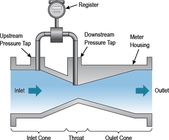
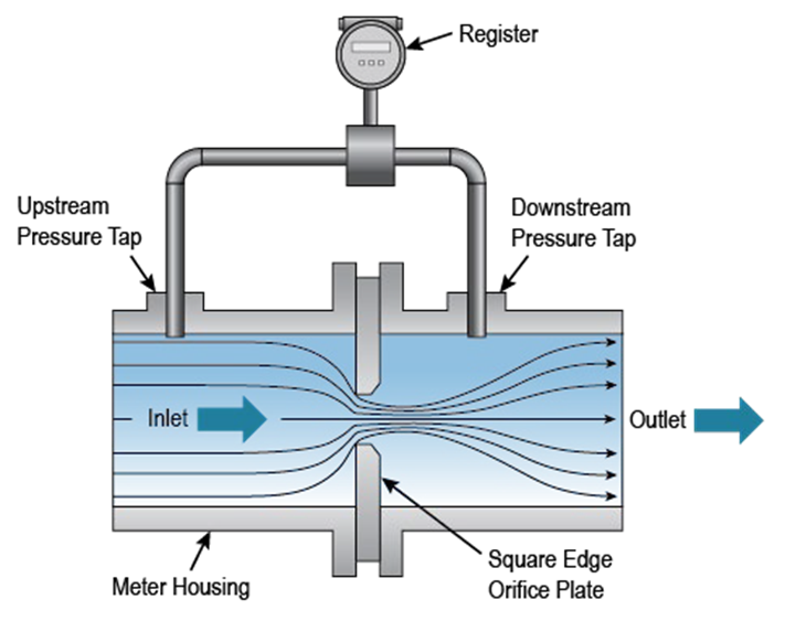
Differential pressure meters work by restricting water flow into the meter and measuring the difference in pressure at the inlet and outlet. The differences in pressure are proportional and used to measure velocity which is then inferred into a volumetric number.
Types: There are two types of differential pressure meters” 1) Venturi and 2) orifice plates.
- Venturi meters restrict water flow by gradually decreasing the tube diameter as the water flow approaches the middle of the meter. The meter takes two measurements: one at the inlet of the meter and one near the narrowest section of the meter. The difference in pressure is proportional to the rate of flow.
- Orifice plate meters rely on a precisely manufactured plate inserted between two flanges to restrict water flow and induce a pressure drop. Suspended particles—regardless of size—abrade the plate over time and enlarge the orifice. This process diminishes the accuracy of the meter. It is imperative that orifice plates be inspected regularly to prevent the occurrence of excessive wear. The frequency at which inspections should occur will depend on water quality and use of the water line.
Applications: Differential pressure meters are used on large water lines in high-flow applications in which variations in flow rate are low. This meter type is most commonly found in larger water distribution systems.
Selection Tips: Differential pressure meters require sufficient space for flow conditioning straight pipe runs installed upstream and downstream of the meter. They are typically less expensive than other types of meters. Common differential pressure meter sizes range from ¼” to 84”. Maintenance, regular testing and calibration, and replacements of orifice plates are all required to attain accurate readings. Costs of differential pressure meters are comparable to the costs of turbine meters.