Metering Objectives
When considering advanced electricity meters at a site, the most important question a facility manager can ask is: what are my metering objectives? Different objectives will lead to different decisions about which advanced electricity meter best suits the facility’s needs. Some refining questions include:
- What are the most important use cases for the site’s electricity meter data?
- What level of detail is required? (E.g., whole-building versus end-use metering)
- What measurement parameters are necessary to collect?
- Is the metering application temporary or permanent (e.g., short-term monitoring or run-time measurement versus long-term metering)?
- What level of accuracy is required (e.g., a higher ANSI C12.1-2024 accuracy class may be required for tenant revenue billing rather than for spot measurement of HVAC equipment)?
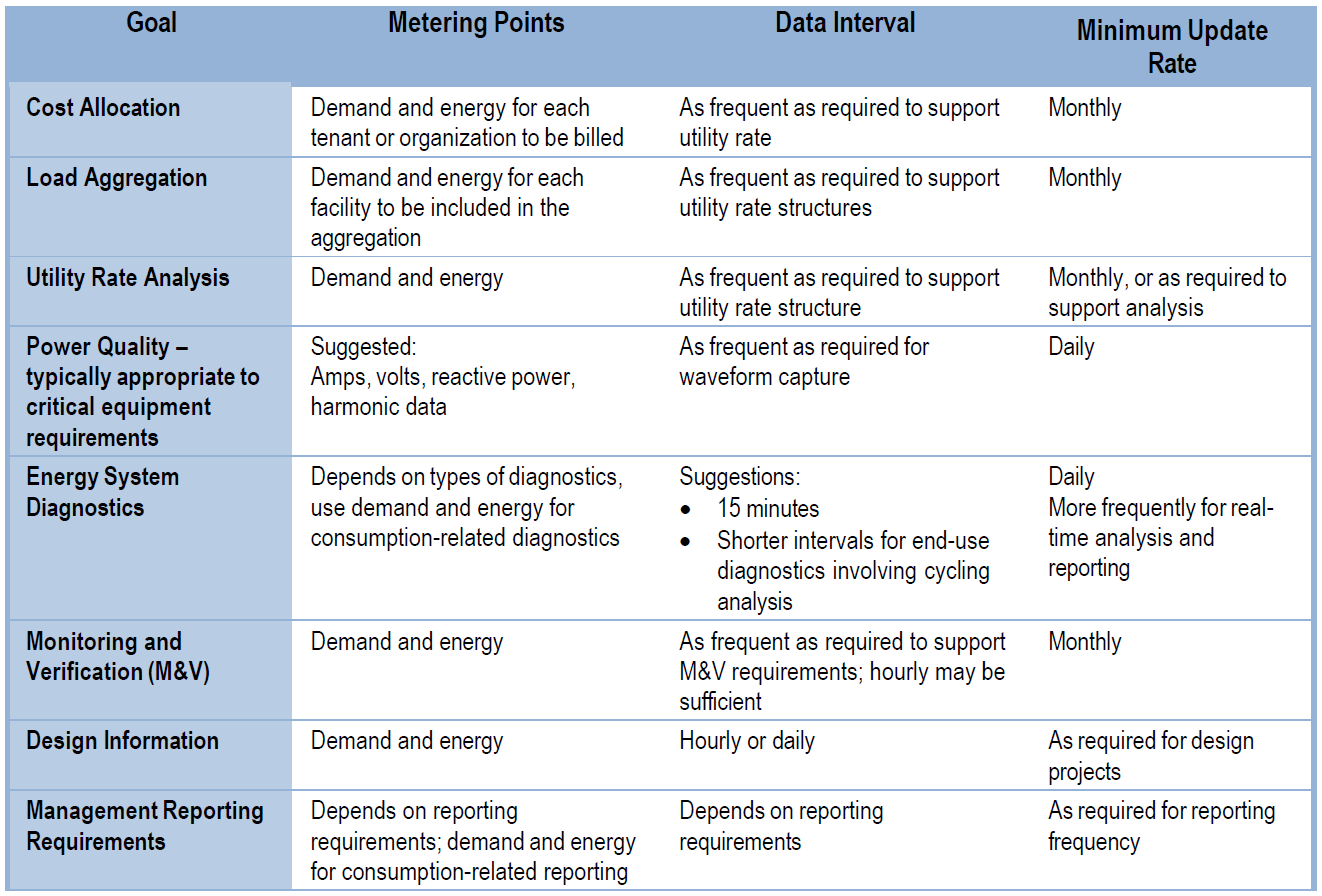
Table 5 presents various electricity metering objectives along with the types and frequencies of electricity data required to support them.
Advanced Electricity Meter Technology Selection
Selecting the appropriate advanced electricity meter starts with the intended building application. Advanced electricity meters come in a range of different specifications and capabilities, and not all advanced electricity meter products will be appropriate for each situation. Important considerations are included in the following sections.
Classification of Electrical Load to be Metered
Meter configuration will vary depending on the electrical service type and the load to be metered. Relevant properties of alternating current power distribution systems include frequency (60 Hz is standard in the United States), number of phases (one or three), number of wires, presence or absence of a neutral wire, voltage rating, and circuit load capacity. The meter inputs must be configured to work with each electrical service type.
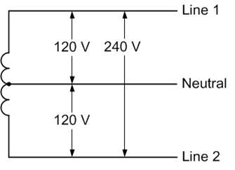
Residential service is commonly 120V, single-phase, and three-wire, including a center-tapped neutral wire.
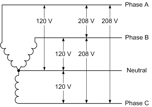
Commercial and some light industrial service is typically 120/208V, three phase, and four-wire wye. For buildings with larger HVAC systems or other inductive loads, 277/480V service is provided.
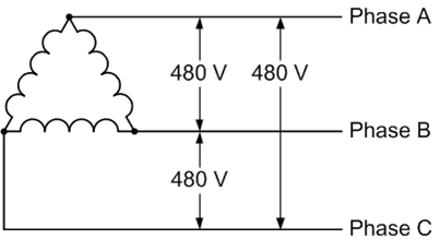
Industrial facilities with numerous large inductive loads typically receive three phase, three-wire delta service, with voltages varying between 240 to 600 or higher.
It is critical to identify the classification of electrical service to each building as a first step in determining which meter(s) may be appropriate for the application. At some buildings, there may be multiple classes of electrical service that serve different loads within the building. This could occur when the building is primarily designed for administrative use but includes a shop wing, for example.
Selection of Current Transformers
An important part of selecting the appropriate meter for the class of electrical service involves connecting the right current transformers (CTs) for the load. CTs are used to measure current on electrical circuits. A CT is placed around a conductor and the magnetic field created by current passing through that primary conductor induces a secondary, proportional current in the CT conductor. That lower secondary current can be read according to a fixed ratio between primary and secondary conductors (e.g. 100:5), where a current of 100 amps in the primary conductor results in a secondary current of 5 amps in the CT circuit. Current rating and accuracy classes vary between CTs, so it is important to select CTs that can perform satisfactorily under the full range of expected operating conditions. The analysis of operating conditions should include minimum, average, and maximum expected loads on the circuit. The number of CTs required will vary depending on class of electrical service and the load to be measured; for example, when metering electrical service at the distribution panel in a residential setting, two CTs are required—one on each 120-volt line into the panel. An additional CT would be required for three-phase electrical service.
There are two main types of CTs: conventional solid or split-core CTs, and Rogowski coils. Conventional CTs are typically used in lower-amperage applications (<200 amps) on standard conductors, whereas larger, flexible Rogowski coils can be used in high-amperage applications on various form factors such as large busbars and oversized cables or cable bundles. Conventional solid core CTs are generally less expensive than split-core CTs, but they require the electrical conductor to be fed through the CT core loop, which would entail disconnecting an existing conductor in metering retrofit applications. Often in these cases, a split-core CT is preferable as it allows the CT to open and re-close around a conductor without the need to temporarily disconnect the conductor. Solid-core CTs are more commonly used in new construction when electrical metering needs are identified from the outset.
Measurement Accuracy
Advanced meter measurement accuracy is a function of both the meter itself and the accuracy of the connected instrument transformers. Each component contributes to overall measurement error. ANSI C12.1-2024: Electric Meters – Code for Electricity Metering is the current edition of the American National Standard that specifies acceptable performance criteria for new types of AC watthour meters, demand meters, demand registers, pulse devices, and auxiliary devices. It also describes acceptable in-service performance levels for meters and devices used in revenue metering.
The standard defines three meter accuracy classes: Class 0.5, Class 0.2, Class 0.1. The class value corresponds to the maximum allowable measurement error; for example, a Class 0.5 meter must have a measurement error within 0.5 percent of true value at full load under unity (1.0) power factor.
The accuracy of an instrument transformer is dependent on the secondary burden, measured in ohms impedance. The burden rating indicates the maximum allowable impedance that may be connected to the secondary of the instrument transformer without exceeding the specified accuracy. Impedance on the secondary arises from characteristics of the secondary wire (e.g., length, size) and the type of meter itself. IEEE standard C57.13-2016 describes standard requirements for instrument transformers.
CTs can be divided into two accuracy classes: metering accuracy CTs and relaying accuracy CTs. Metering accuracy CTs are designed to be highly accurate over almost the full range of very low current to the maximum current rating. Relaying accuracy CTs are less accurate than metering accuracy CTs, but they are designed to perform over a wider range of current. Additionally, they must be reasonably accurate even in overcurrent conditions.
A metering accuracy CT classification consists of three parts:
- Accuracy (%) – the CT is rated by the manufacturer to be accurate within this percentage of its rated ratio value for a primary current of 100 percent of rated ratio.
- CT class – this is always “B” for metering accuracy CTs.
- Maximum allowable burden (ohms) – the maximum allowable impedance that can be imposed on the secondary without causing an error greater than the specified accuracy.
Example: A CT with a rated ratio of 300:5 has an accuracy classification of 0.3B0.2. This means the CT is accurate to within 0.3 percent of 5 amps for a primary current of 300 amps if burden on the secondary does not exceed 0.2 ohms.
It is important to properly characterize the normal operating range of current on the primary before selecting an electricity meter and instrument transformers.
Electricity Meter Characteristics and Capabilities
When selecting an advanced electricity meter, there are many characteristics and capabilities to consider for each specific metering application. An advanced electricity meter should cost effectively meet the requirements of the desired metering application and deployment environment without delivering unneeded functionality. Some characteristics to consider when selecting an advanced meter include:
- Phases
- Power Supply
- Inputs/Outputs
- Display
- Comms Ports
- Comms Protocols
- Measurements
- Alarms
- Fault Detection and Diagnosis
- Onboard Analytics
- Custom Programming
Not all advanced meters that are functionally capable of meeting the requirements of an application are cost-effective nor appropriate; for example, a $20,000 advanced electricity meter capable of monitoring and analyzing microsecond-length power quality fluctuations is likely not appropriate for tracking electricity use in an unconditioned storage building, as the potential savings that could be achieved through effective meter data analysis would never be large enough to recoup the initial investment.
To assist in evaluating the cost-effectiveness of advanced metering at a specific building or site, visit the Advanced Meter Cost-Effectiveness Calculator website.
Maintenance
Maintaining the associated metering electronics has been substantially reduced and reliability has increased due to a shift towards digital metering. Environmental conditions play a key part in the longevity and reliability of the components (e.g., temperature, vibration). The current and potential transformers are generally maintenance free, provided they are originally designed for the operational and environmental conditions. The integrity of electrical connections should be checked periodically in accordance with National Fire Protection Association (NFPA), National Electric Code, NFPA 70 (NFPA 70-2023), and manufacturer guidance.
Data Output/Communications Considerations
For the building-level meters, a common energy data output is the calibrated pulse (e.g., pulses/kWh). For more advanced features and data collection, a more advanced communication protocol, such as Modbus, LonWorks, or BACnet, may be required. These data are usually stored at the meter in the prescribed time-series format or may be real-time communicated to a data acquisition system that assigns a time stamp. At periodic intervals (at least daily), the data are accessed through one of a variety of communications options. These data are then downloaded to a database for future processing.