Recent Progress
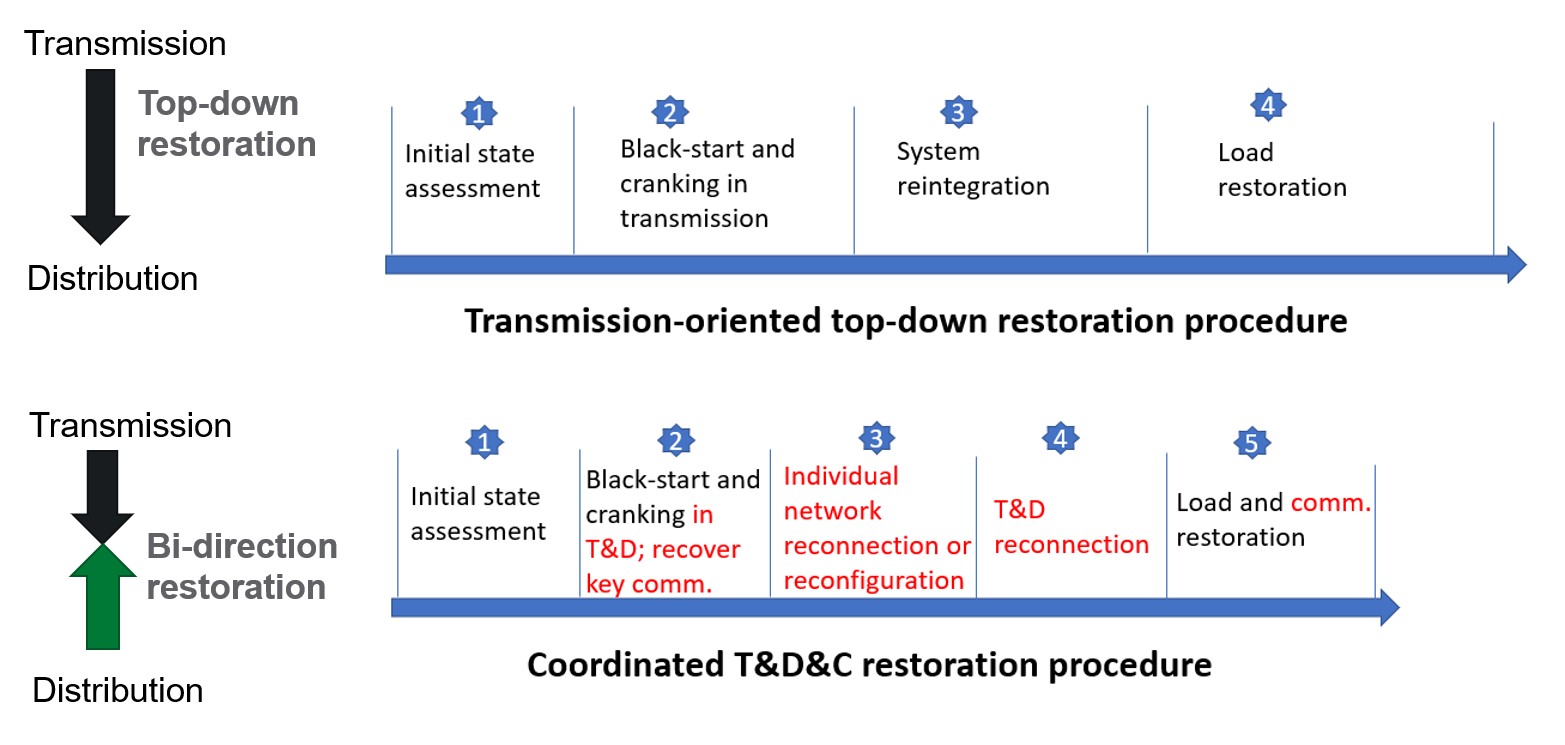
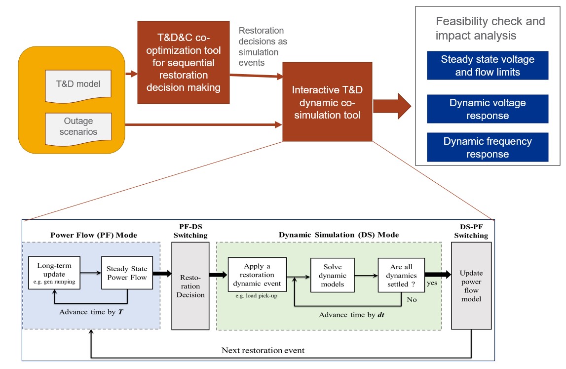
We evaluated the benefits and impact of our proposed coordinated T&D bi-direction restoration method, with a direct comparison with the traditional transmission-oriented restoration method as illustrated in Figure 5. The tools that we developed in previous quarters for coordinated T&D system restoration decision-making, feasibility check and impact analysis(illustrated in Figure 6) are leveraged for this effort.


During the implementation of our method, we have considered two major features:
- Including the transmission line electrical distance along the cranking path as a penalty when determining the sequence of energizing non-blackstart (NBS) units.
- Optimizing the DERs output (and charging for energy storage-based DERs) for by introducing the look-ahead time window with estimated grid reconnection time.
Metrics for quantifying the benefits and impact of the restoration method include:
- Restoration time: the cost of outage increases exponentially over time, thus it is critical to minimize the restoration time.
- Number of voltage violations during feasibility check: to quantify Quality of the restoration solutions.
The expected benefits of our approaches include:
- Overcoming the difficulty of procuring traditional generators as blackstart units and expanding the choices of blackstart capabilities across the grid.
- Significantly reducing (e.g., by half) the system restoration time by realizing distributed restoration (i.e., the system with outages is first divided into several islands in order to carry out restoration in a distributed manner), with aggregated DERs providing extra blackstart capabilities to the system. This will also contribute to reducing the unserved energy.
- Improving the quality of the restoration solutions by avoiding common issues such as over voltage and low frequency violations.
1. Evaluation Result
For this evaluation, an integrated T&D system is constructed by attaching IEEE 37 bus distribution feeder at each of the three substations (load buses) of IEEE 39 bus transmission system as shown in Figure 7. Each substation bus is connected to the distribution feeders via a substation transformer. This system has 10 generators, in which the one at Bus 31 is assumed to be the blackstart (BS) unit and others are non-blackstart (NBS) unit, and 46 transmission lines. The generator parameters related to the black-start process is given in Table 1.
The nominal load for the IEEE 37-bus feeder is 2.457 MW. However, with a DER penetration of 50%, the net load is equivalent to 2.457MW/2 =1.2285MW. In order to properly represent distribution systems at the transmission bus (substation), a scaling factor has been introduced that is equal to the original transmission load in the network divided by the nominal feeder load. For example, the load at bus 4 is equal to 500 MW. Therefore, a scaling factor of 500/1.2285 = 408 is used. The feeder loads are multiplied, and the line impedances are divided by the scaling factor to achieve an equivalent feeder.


The nominal distribution load for the IEEE 37 node system is 2457 kW. However, depending on the DER penetration level, the total net load seen by the transmission (at the substation) would be less than the nominal value. For example, if we have a penetration level of 50%, the net load is 2457/2 = 1228.5 kW. To create a load that is proportional to the transmission load, we introduce a scaling factor that is equal to the transmission active load portion divided by the net load.
1.1 Comparison Results
1.1.1 Generator energization sequence considering electrical distance between
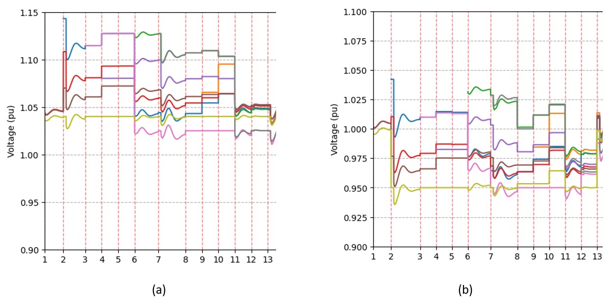
Traditional methods are focusing on maximizing generation capacity during the blackstart stage while neglecting the cranking path distance. In contrast, our method is formulated to maximize generation capacity while minimizing the electrical distance between the energized backbone and new NBS units. Figure 9 shows the optimal generator-energizing sequence and corresponding paths with the traditional and our methods. With traditional methods, NBS units with larger size but quite far away from the BS unit at Bus 31 are prioritized to be energized. For example, the NBS units at Buses 35 and 36 are energized before the NBS unit at Bus 32. This tends to cause more voltage violations during the early stage of the restoration stage due to the charging of lightly-loaded transmission lines as illustrated in Figure 9. With 1.075 pu as over-voltage violation threshold, there are ten steps with voltage violations. In contrast, our method will prioritize nearby generators by increasing the penalty of the electrical distance along the cranking path. For example, NBS unit at Bus 32 is energized before those at Buses 35 and 36. This, in conjunction with generation setpoint optimization, can help mitigate the voltage violations along light-loading transmission lines. There is no voltage violation. In this way, our method can achieve improved quality of the restoration solution.


1.1.2 Blackstart results with both approaches
Looking closer at the results shown above, we can notice that it took some steps to energize generators 33, 34, 35, and 36. This is common in practice when certain areas in the system do not have BS units or resources to provide auxiliary power to energize their NBS units. Therefore, they have to wait for power support from neighboring areas. With the advent of DERs, it is common to utilize these resources to energize NBS units in areas that does not have (or has but could be not reached due to damage in transmission network). This allows parallel black-start energization processes which can reduce the total restoration time significantly. The utilization of DERs is under the assumption that these resources can establish and support voltage in the system. That is, DERs have to be either based on conventional generators (like diesel units) or inverters with grid-forming capability. Moreover, DERs are based on renewable energy must have energy availability to supply the auxiliary load of generators reliably. In this work, we consider DERs that are based on diesel generators, PVs with available solar forecast, and energy storage systems. We assume a good percentage of DERs connected at distribution networks connected at buses 4 and 20 are grid forming and can serve as BS units.
Given that unit 31 is a BS unit, we continue to use it. With additional blackstart capabilities, the whole system can be divided into 3 islands with a similar size to realize parallel blackstart as shown in Figure 10.
The maximum restoration time is 13 steps with our method. In contrast, the traditional method requires 37 steps to complete the whole blackstart process. This means our method can reduce the total outage times by about 3 times.


